Engineering is more than just book knowledge, it’s important to tinker and experiment so we’ve created some activities for Unit 1 which covers Ammeters, Watt meters and Voltmeters. All these activities require adult supervision. These can be done in a classroom, lab or at home.
You can see both of the activities below quickly in the Unit I video, however the video moves too quick to fully explain how to build these, so use our text below.
Video here: Galvanometer section at 2:04 min >
BUILD AN AMMETER!
This is your chance to build your own instrument and experiment with how well it detects electricity.
Concepts taught int his activity:
- Basic electromagnetism – illustrate how energized wire creates a magnetic field, see clear evidence of its effects
- The Left Hand Rule – this rule is the basis for electric motors. This activity shows in a very basic way how movement is generated by putting electricity through a wire and how it reacts in an electromagnetic field.
- How moving-coil galvanometers work. This type of meter is used all over the world. Notice how the wire meter you build is much easier than the compass type of meter. See how the moving-coil galvanometer was a superior tool and caused the advancement of technology.
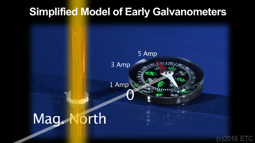
PART 1: THE COMPASS AMMETER
We will build an electric meter using only a compass and an energized wire coil. This is how the first electric meters worked for over 60 years.
Materials:
- Cardstock or Cardboard square
- Pen or marker
- A working compass
- Magnet wire (insulated wire)
- Battery
- Cut a square of cardboard or cardstock 6″ x 6″
- Tape the end of the cardboard to a table with half of it sticking out
- Cut a slit in the cardboard
- Coil the wire 10 times in a loop about 10″ in diameter (8.5 ft of wire). Leave some loose wire at the end for hooking up to a battery. Tape the coil so it stays tight.
- Slide one side of the coil of wire into the slit in the cardboard allowing you to have the bundle of wire up and down.
- Tape down a compass next to the coil so that magnetic north points close to but not at the wire coil. See the photo below.
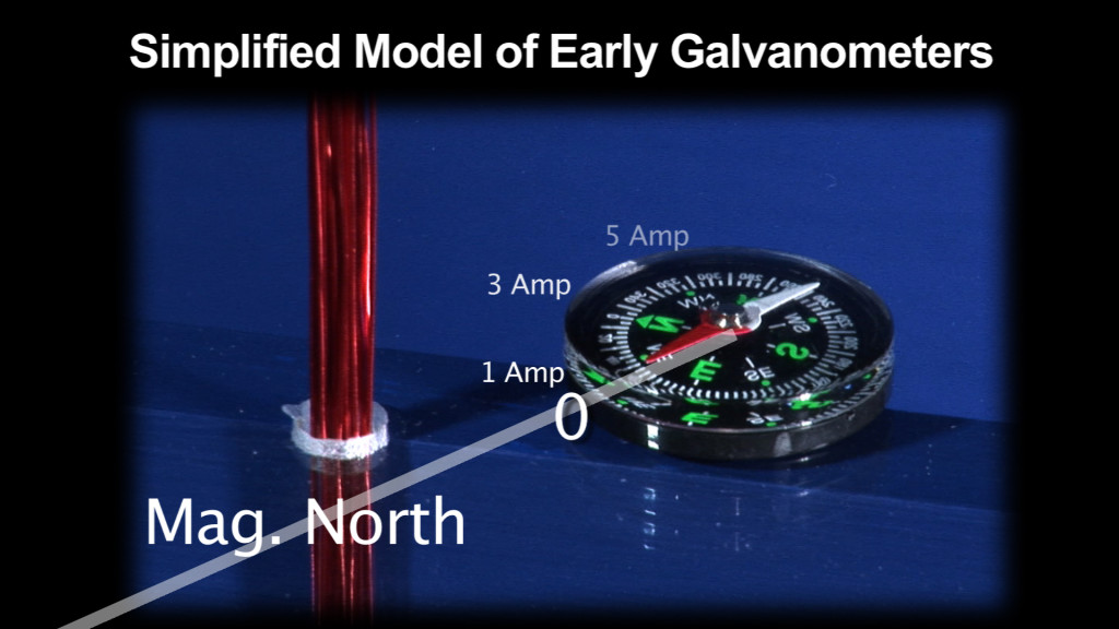
- Now its time to see the meter at work! Connect the coil up to the battery with one side to (+) and the other side to (-). Notice how the magnetic needle deflects. Mark with a pen where the needle goes.
- Now disconnect your wire from your battery. If you want to play with electricity you should always remember to disconnect power before working with a circuit! Take and uncoil 5 coils off your wire coil. Re-tape your 5 coils and reset it into the cardboard.
- Now reconnect your power. What happens differently? You will see that the compass acting as our “meter” shows only a fraction of the reading. This proves that adding more insulated wire coils to the same power source creates a stronger magnetic field.
Problems with this meter:
Now you will learn about why engineers wanted to invent something better, and eventually Edward Weston and Elihu Thompson did invent a better meter.
- Disturbance in the force! Take a permanent magnet or heavy piece of metal, put it close to your compass and watch how it messes up your reading. Many large pieces of equipment that need testing create disturbance in the electromagnetic field. The Earth itself has magnetic or iron-bearing rock that will also disturb the galvanometer.
- Portability: Look at the device you have made and imagine having to carry that somewhere to do a test. You’d have to spend time setting the meter down and aligning the needle to magnetic north. In some environments like a car garage your meter would become smashed eventually as environments can be very rough.
- Lack of versatility: This meter may work for the D battery, but what if you wanted to use it to measure your car battery? You could get badly burned and start a fire because this is much more powerful. You’d have to specially design a meter for the car battery which uses fatter wire and a different number of turns. You’d need a specialized meter for every use. In the days of the telegraph that is exactly what they had to do. An engineer and tech had to carry several fragile instruments with glass across the country to test sections of telegraph lines.
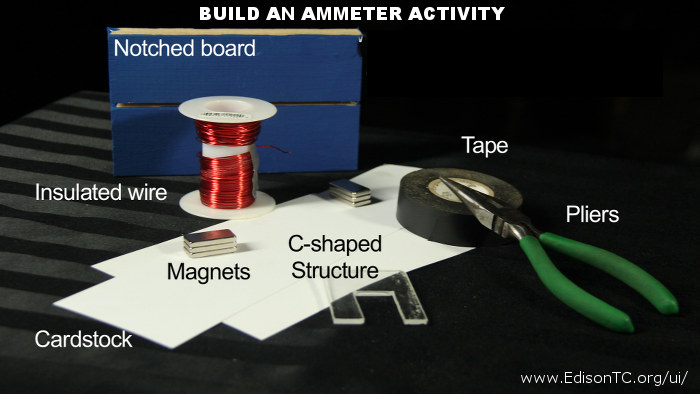
PART 2: THE MOVING WIRE AMMETER
This was the next step in meter technology and it quickly replaced the old galvanometers. This meter uses the Left Hand Rule to move the meter’s needle, this is the same concept that makes motors run.
Materials:
- Electrical tape
- Insulated wire
- Strong rectangular magnets
- Notched wooden board
- Pliers
- Cardstock
- C-shaped rigid structure (see photo), it can be made of a non-metallic substance
- Variable DC power source or multiple D batteries
Take a cut of a single insulated wire about 2′ long and make a rectangular shape according to these photos. The section that will move is about 8″ long. It will rotate through a hole in the cardstock. That “hinge” must be firmly planted.
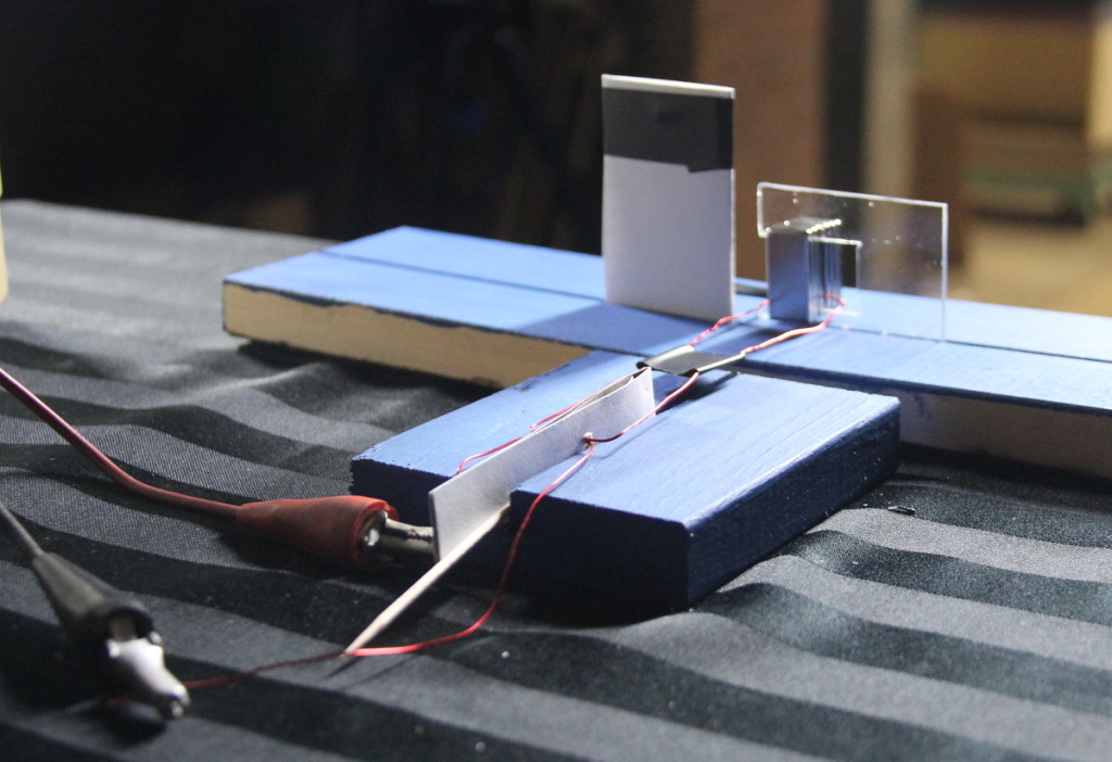
Above you’ll see that we press the loop of wire together and put tape on it so that will become the indicator.
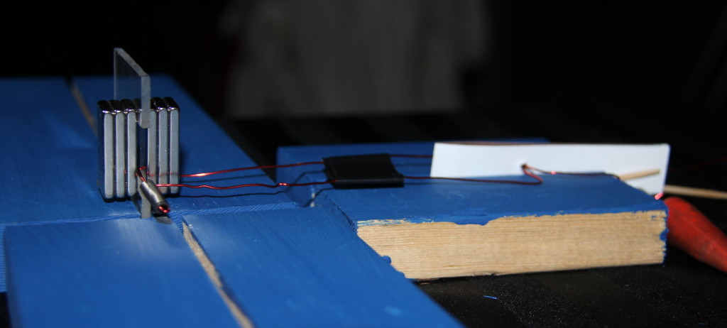
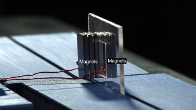
Once your wire loop is set up firmly you can insert the wire loop between the two magnets. Strong rare-earth magnets are necessary. If these snap together quickly they can pinch your skin and it can really hurt, so handle them carefully. Using the C-shaped holder which you built have the two powerful magnets stick to each side, using the natural attraction to keep them stuck in position. Position your wire in the air gap in between as you put it together.
Tweak the wire so gravity holds it down. If the wire is springy it may want to sit up mid-magnet. You want it to lay close to the bottom.
When it’s all ready you can hook the wire up to a power supply or a D battery. Consult with a qualified adult to use the right power supply. If you use the wrong one you can cause a fire, or it will be too weak and nothing will happen.
RESULTS:
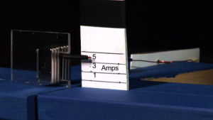
You should see the indicator move upward. You can put a piece of cardstock in the slot so that the meter points to a certain level. If you are using a power supply that displays a value you can mark the amps on the card as in this photo.
Oh No! It wants to move downward, not up!
If you hooked the wires up backwards the wire will want to move down away from the magnets. This is why when you are using actual ammeters you need to connect it according to its polarity.
It doesn’t move at all!
Check your connections to make sure all your contacts are touching. Also if you are using varnished insulated wire like in our photo you need to scrap off the insulation before attaching alligator clips to it.
If all your connections are ok, than your power supply is not enough. Add more D batteries in series if you are using D batteries.
Experiment:
Once you see movement with your home-built meter, you can experiment. You can try other power supplies, or if using batteries you can attach more of them.
You’ll discover that your meter only works with a given range of Amperage. So this meter is useful if you know that the amps your testing in a given circuit are in the range. In the old days they had to carry several ammeters, you could measure with the ones that measured large quantities first, than work your way down to the meter that was the most sensitive. Many times techs and engineers would put the lower level meters on too high of a line and they’d burn out the meter. The coils in the meter than had to be replaced. Your home-built meter is not designed to burn out safely so don’t try this type of experimentation. You can use a digital meter and see how this bracketing works.
What about AC power?
Don’t hook this up to a wall outlet as it will short and cause a fire. If you could slow down AC power to less than 60 Hz and lower the amps you could see the wire wiggle up and down as the polarity switches. The first Ammeters only worked on DC power.
In the 1880s when they invented this type of meter AC power was already getting a start. They had to invent a rectifier to make their meters work. The rectifier converts the AC to DC signal.
PLEASE refer to the video to see how these experiments look when completed.
Useful Links:
Go back to the start of Unit I
Go back to the Galvanometers page