Until vacuum tube and semiconductor meters most ammeters and voltmeters were based on magnetics. The “galvanometer” is a term for many types of meters that use magnetically deflected indicators.
The Science:
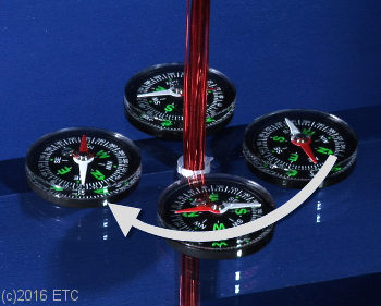
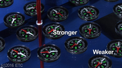
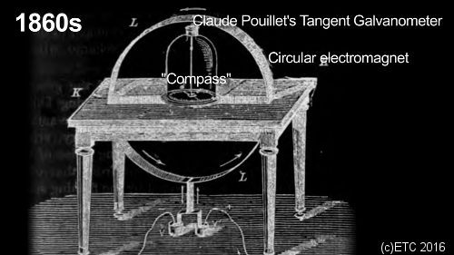
Our video stills here illustrate how a galvanometer works in the clearest possible way. When you energize a wire or coil it creates a magnetic field. If you place compasses around that wire (perpendicular) you will notice that the magnetic north points in a circular patter around the wire. As you go out from wire the strength of the magnetic field decreases.
To build a meter that can “see” small weak frequencies you would increase the magnetic field by coiling the wire more times.
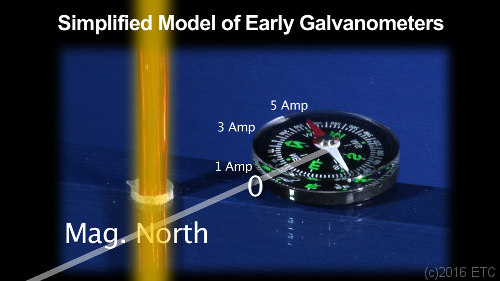
In the graphic above you’ll notice that we manually placed the compass in a position where the energized coil of wire deflects the needle. Since we were using a power supply with known amp value, we could have put marks on the compass to show positions at different amp levels. Then if we had a mystery source which we knew was between 1 and 5 amps, we could have used it to energize the same coil, and this simple compass could have told us the approximate value of that source!
See our video excerpt here about this topic.
Pre-1880s
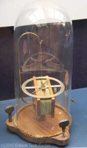
In the 60 years before the explosion of the electrical industry (1880s), simple and inadequate types of galvanometers were used to attempt to measure current. Most galvanometers found their uses in labs or telegraph installations.
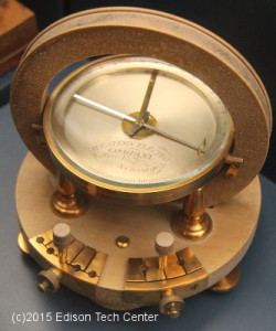
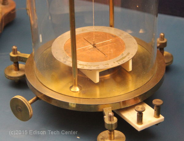
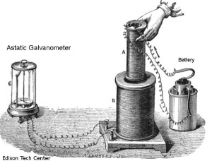
The first galvanometers included the Astatic and Tangent Galvanometer. Calculating the current of a circuit was a mathematic operation based on the meter’s results, there was no needle that pointed to the actual current value. These early meters were extremely fragile and could be inaccurate when effected by surrounding magnetic materials or the Earth’s magnetic field.
Before amplifiers, engineers used string galvanometers to measure small amounts of current. The string galvanometer was a type of Moving Mirror Galvanometer. A small mirror was more sensitive than a needle, it could deflect a beam of light effortlessly and move at the slightest bit of pressure. When combined with photosensitive papers the record of movements of the device could be recorded as a oscillograph.
The Moving Mirror Galvanometer:
- Increased accuracy by having a longer effective needle (produced by light)
- No need to counter balance a physical needle
- Ability to record measurements using photo sensitive paper.
Chester W. Rice from General Electric Research Labs was among many engineers who continued to use mirror galvanometers into the 1930s for cutting edge experiments, however today we do not use this type of instrument.
Overview of Early Galvanometers:
Advantages: Better than nothing, these devices were the first attempt to measure electricity.
Disadvantages: Fragile and accuracy is affected by nearby magnetic materials, complex math calculations were required to calculate amperage in later meters, before the “modern” meter of 1886.
Post 1880s
The early galvanometer became the basis for the “moving coil galvanometer” which was the next step in development. The moving coil type was used as ammeters and voltmeters for the next 100 years. Lets move on to the Ammeter section.
Note: we list sources for all the pages in this unit in our Credits page.
For media licensing see our page here.
