The voltmeter is a key instrument in our world of electrical technology. They are used in everything from x-ray machines to radio transmission, computers to power utility and atmospheric science measurement to the Hubble Telescope. Voltmeters can use magnetic fields, electrostatic fields, and plasma phenomena to measure voltage. In this page we talk about PMMC or moving coil galvanometer type voltmeters which were the first voltmeters and dominated the industry for over 100 years until they were replaced by wide use of digital multimeters (DMMs).
To see the science and engineering of the voltmeter we recommend you watch our short video below, if you saw this video at the start of Unit 1 already you can move on.
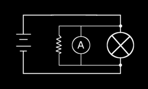
The voltmeter is built on the equation:
voltage = current x resistance
Voltmeters were really measuring the current through a resistor. More sensitive ammeters led to the voltmeter. The Ammeter was developed first because it was easier to measure higher current. In the voltmeter we need to be able to measure the small sample of current.
Ability to measure milli and microamps leads to the voltmeter:

Edward Weston revolutionized the field of instrumentation when he developed the first portable electric meters and a reliable PMMC (permanent magnet moving coil instrument).
Stable permanent magnets and consistent resistor materials are required for accurate voltmeters. Westin’s Manganin alloy enabled stable resistors for use in voltmeters and ammeters. Manganin is made from 86% copper, 2% nickel, and 12% manganese.
From a science perspective Weston found that metals can have a negative temperature coefficient of resistance.
Before the 1870s meters were fragile lab instruments not entirely useful for testing systems. Before the 1870s most electrical installations were for the telegraph where there was not a need for regular measurements. Mirror galvanometers were used to help set up telegraphs. Westinghouse led many of the innovations in voltmeter design with AC pioneer Oliver Shallenberger on the team. Philip Lange and Shallenberger took the galvanometers of the time and added the needed resistors that converted them from ammeter to voltmeter. They redesigned the meters to work with Tesla’s 2-phase system, and later Dobrovolsky’s 3-phase system which ended up being today’s standard.
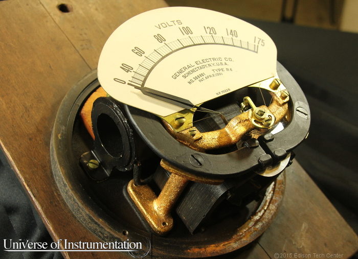
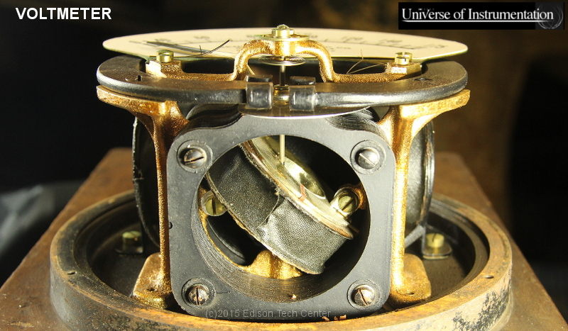
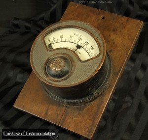 The standard volt and ammeters through most of electrical age were magnetically driven and use a robust “can” design with permanent magnet.
The industry standard of voltmeter for many decades was developed in 1886 by chemist and engineer Edward Weston in New Jersey. Weston’s innovation included a stable permanent magnet and his development of a special Manganin material. See our page on ammeters to read more about the design since ammeters and voltmeters were very close.
Further reading: